Esoteric technology is beautiful
A couple of years ago I found an old video of Maggie Rogers, then a completely unknown NYU music student, nervously playing Pharell Williams a demo of her song "Alaska". Their interaction is adorable and captivating, and equally so was the dancing green point cloud framed in a functional-looking little display sitting behind Pharell.
Who was it designed for? What information was it supposed to show?
The audio vectorscope
An audio vectorscope plots the instantaneous amplitude of an input signal onto a 2D plane - its x and y components representing the left and right channels respectively. They're meant to show a mixing engineer how "wide" their mix is, or if there are any phase issues. Hardware versions are increasingly rare, and they're priced accordingly. They're professional tools. I'm hardly a professional, but I think I could make my own.
My first attempt
A teensy and a display seemed like a good first place to start, so I hacked together a little SPI breakout board and 3D printed an enclosure:
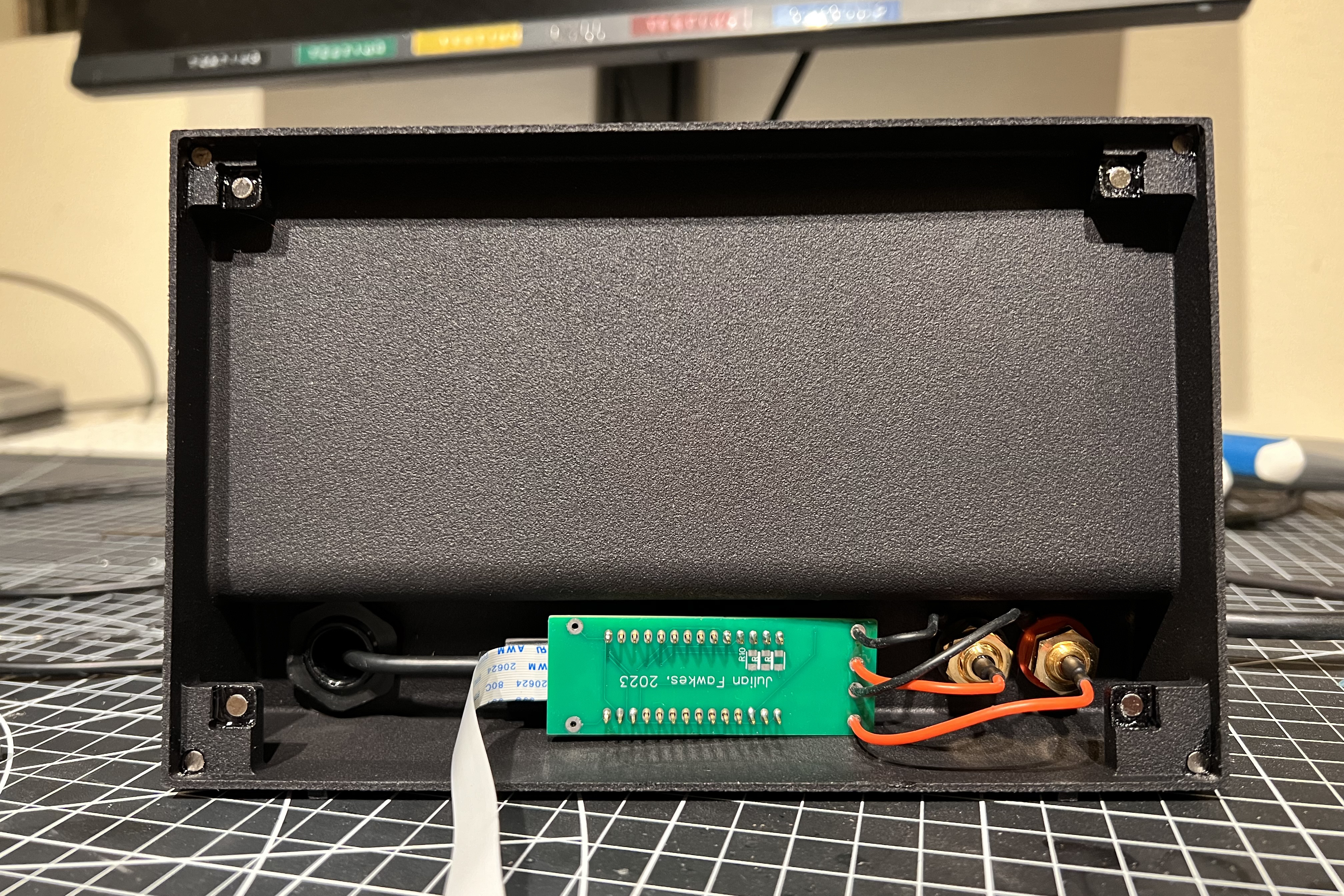
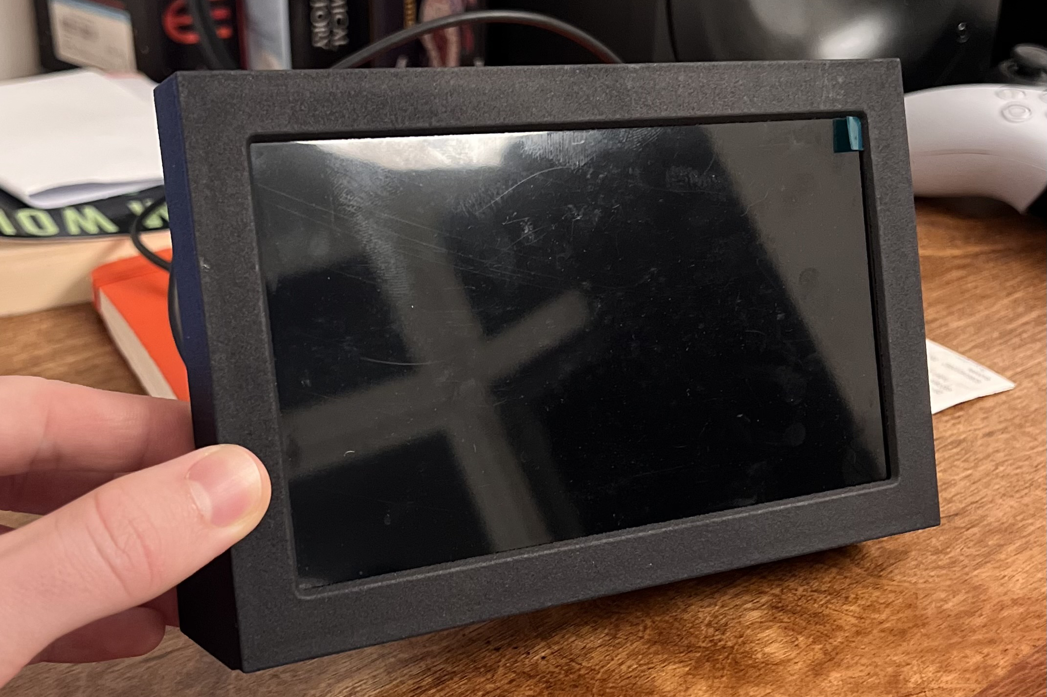
I wasn't particularly satisfied. The enclosure I designed was bulky and inelegant, and the teensy's on-board ADC did not have sufficient resolution or noise performance to show the audio signal with enough clarity.
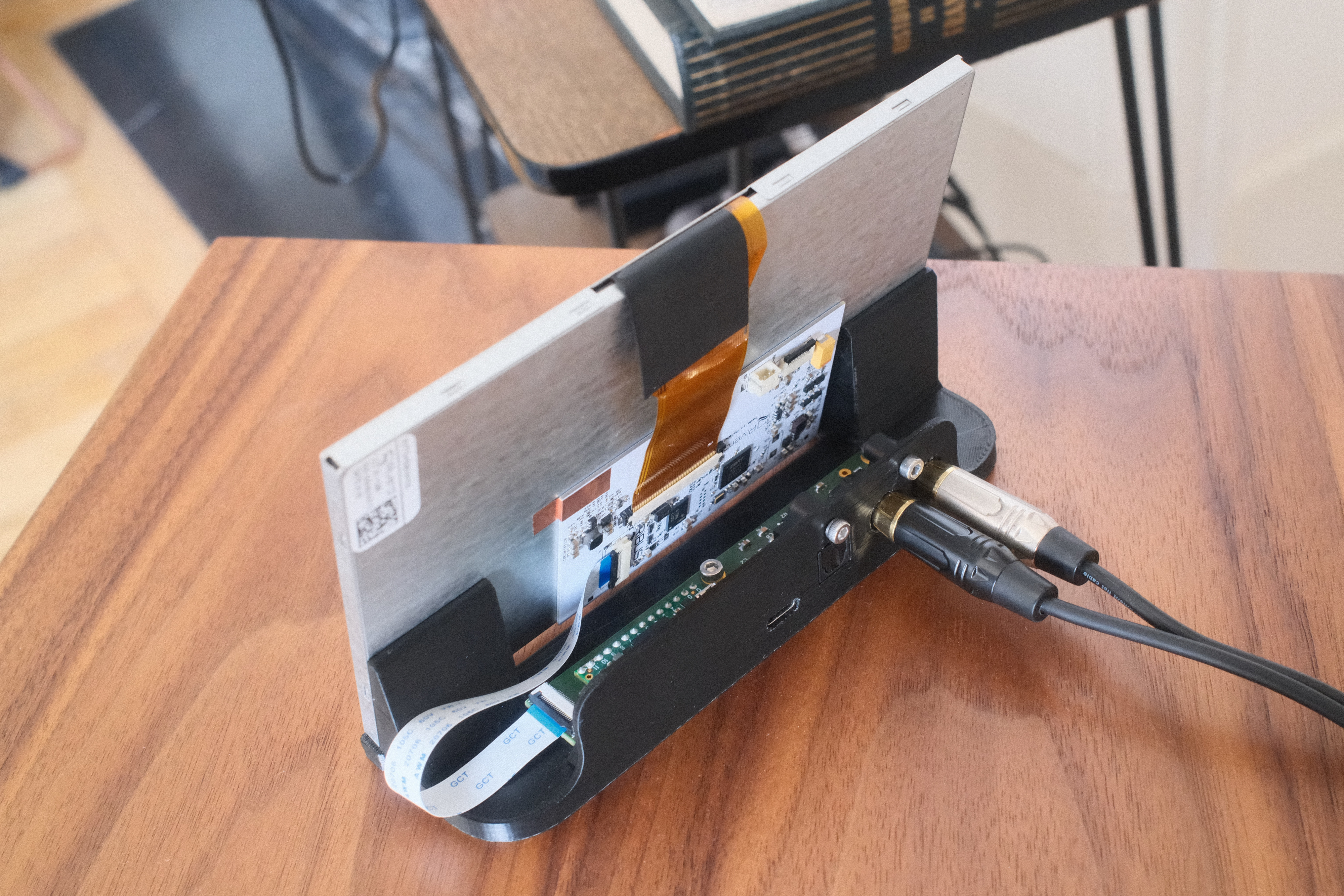
To get it to a point where I would be happy with it, I would need to simplify the enclosure, reduce the electronics' footprint, add an external ADC, and reduce the number of stray wires. To that end, I taught myself how to use an EDA and designed my very first multilayer PCB!
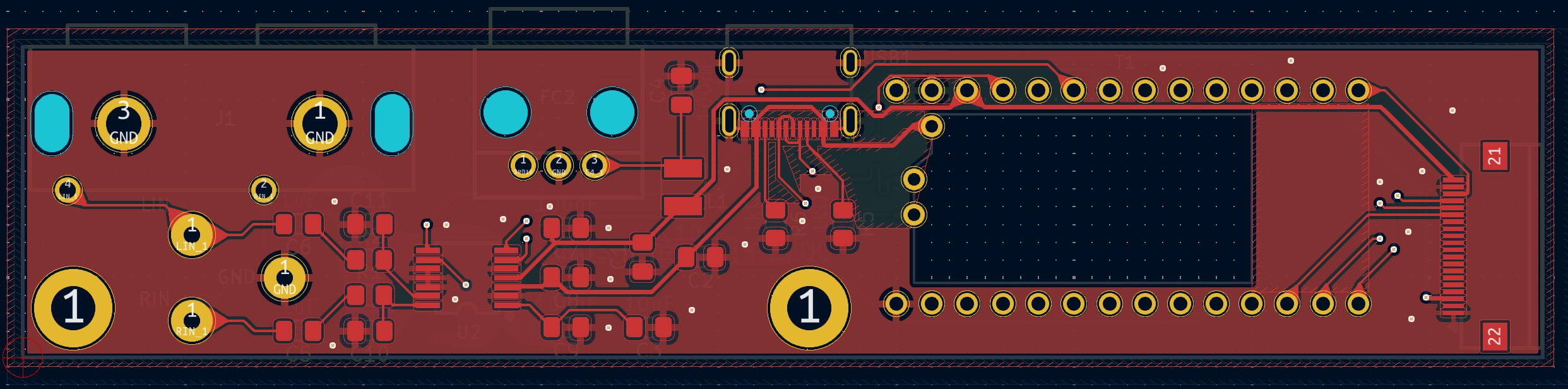
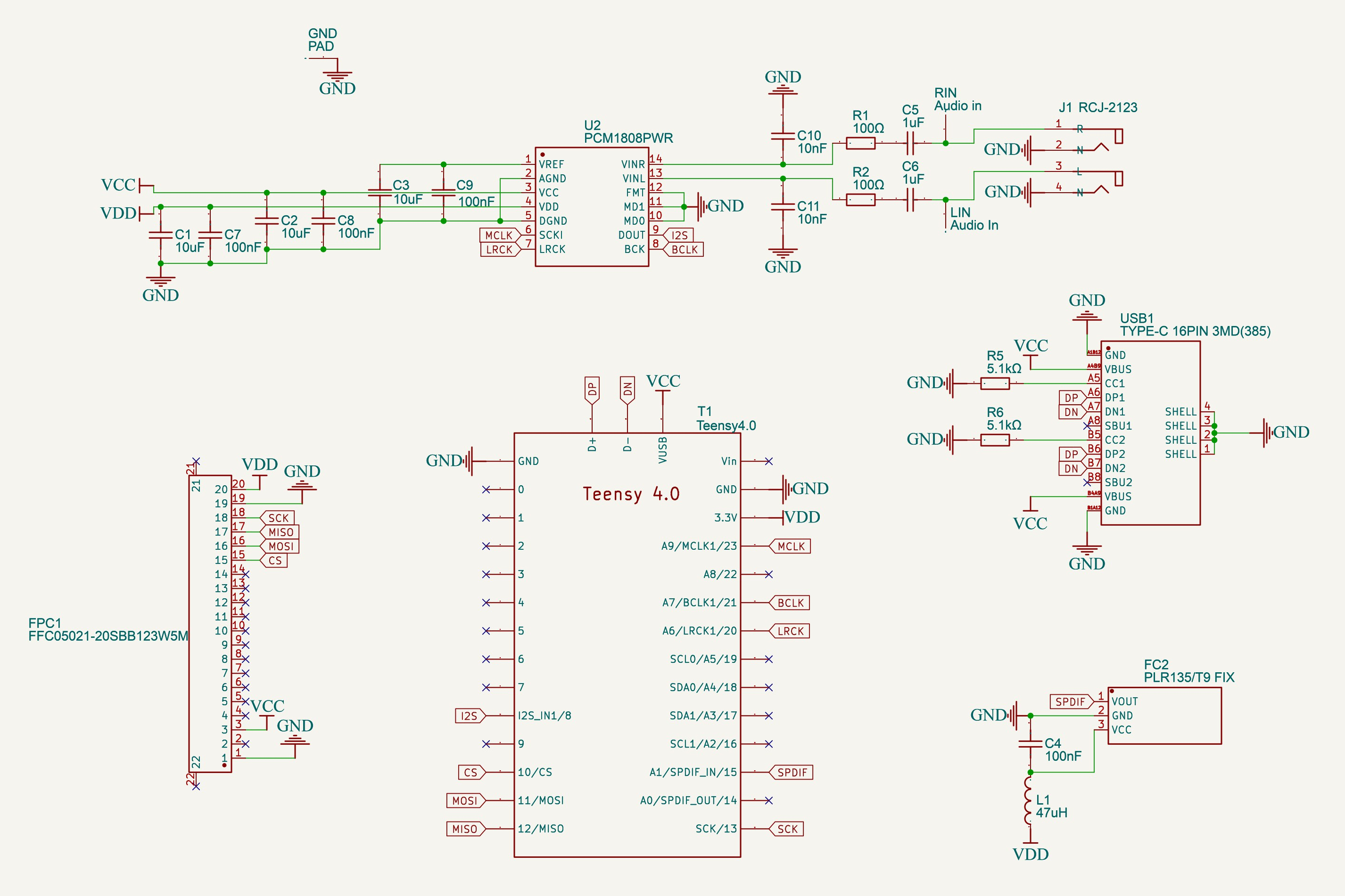
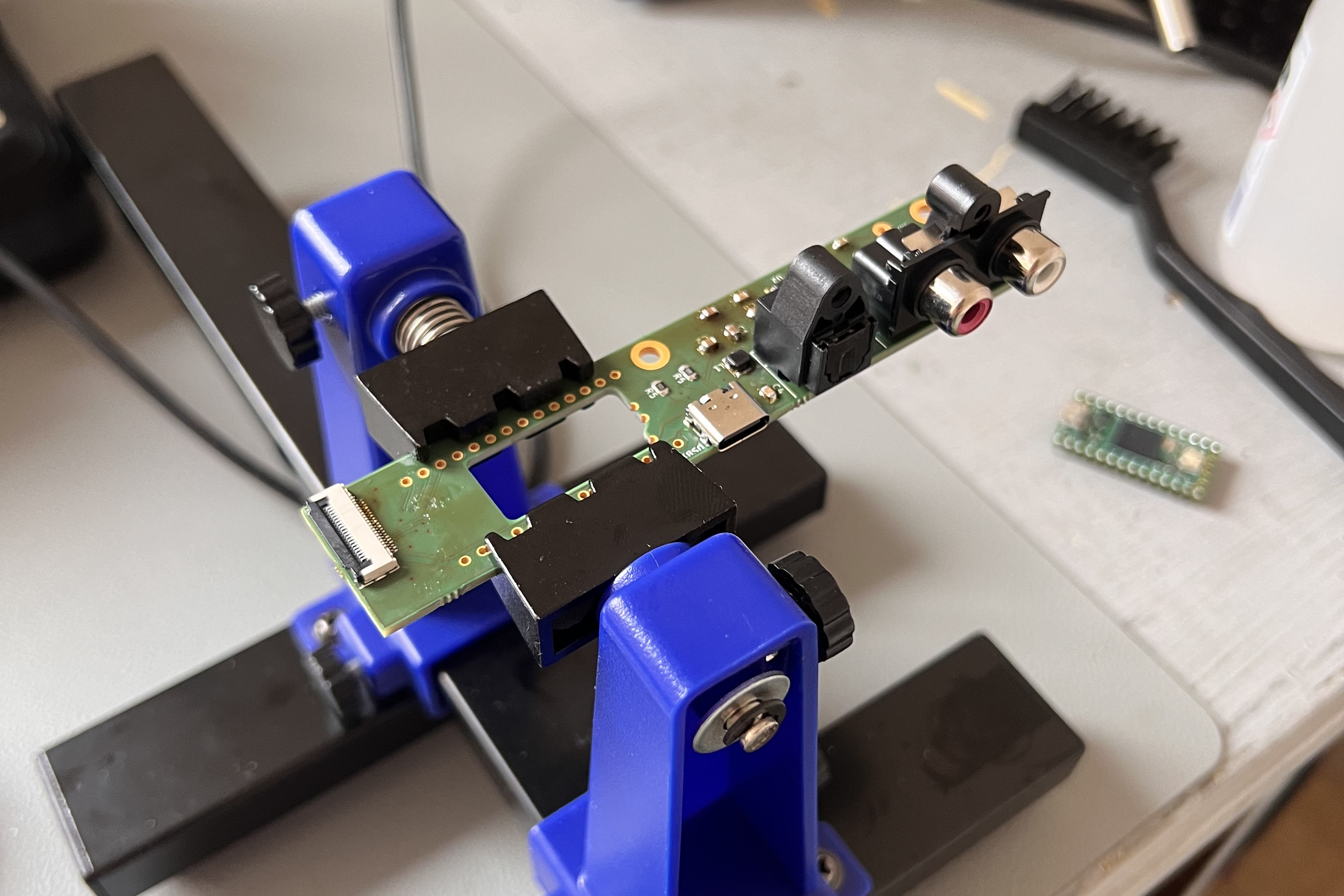
The final board has four layers and consists mostly of surface mount components. Everything is hand-soldered. In order to minimize noise added to the audio signal path, I divided the board into an analog side with low frequency signals and a digital side with high frequency signals.
I'm really quite proud of my first attempt at a fairly non-trivial board. The performance gives the visual quality I was looking for and all of the components hooked up without a hitch.
Letting functional limitations dictate the design
In my first iteration of the enclosure, my goal was to make something with the appearance of a real product. I wasn't willing to sacrifice ease of disassembly, and I only had access to cheap FDM printers. All of the walls and bezels ended up twice as thick as I wanted, and my chunky black plastic enclosure looked more Dell than Technics.
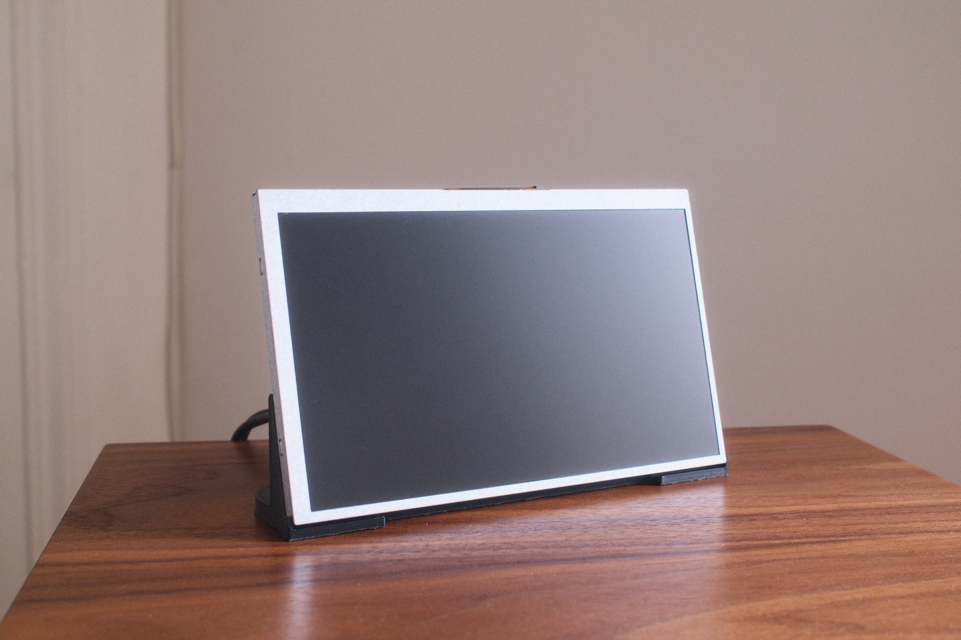
My second go around, I accepted the limitations that my requirements and tools imposed. I left the display's aluminum bezels exposed and fixed it to a very simple base that displays rather than hides the PCB. Everything comes together with screws and magnets, in case of any mistakes or modifications.
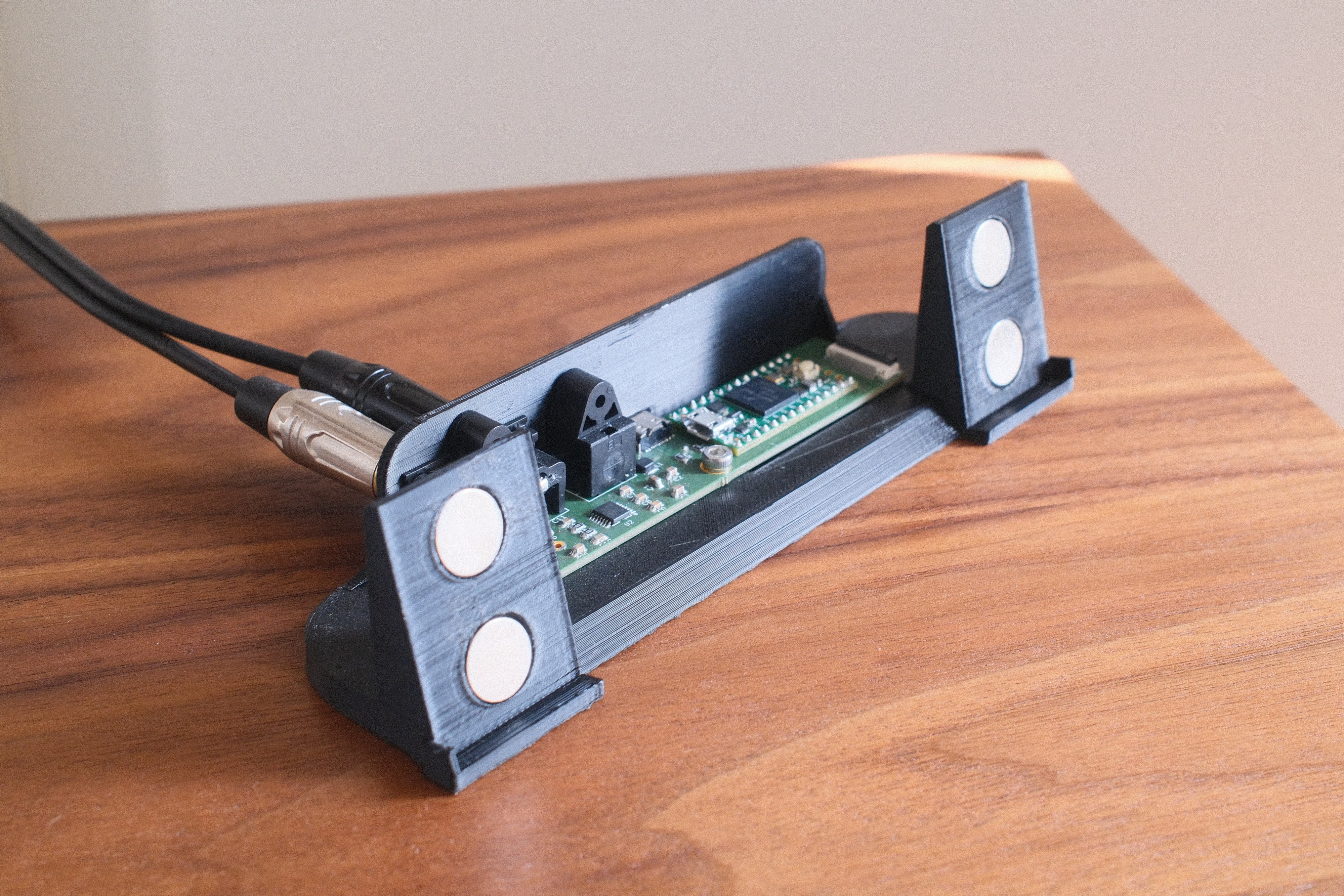
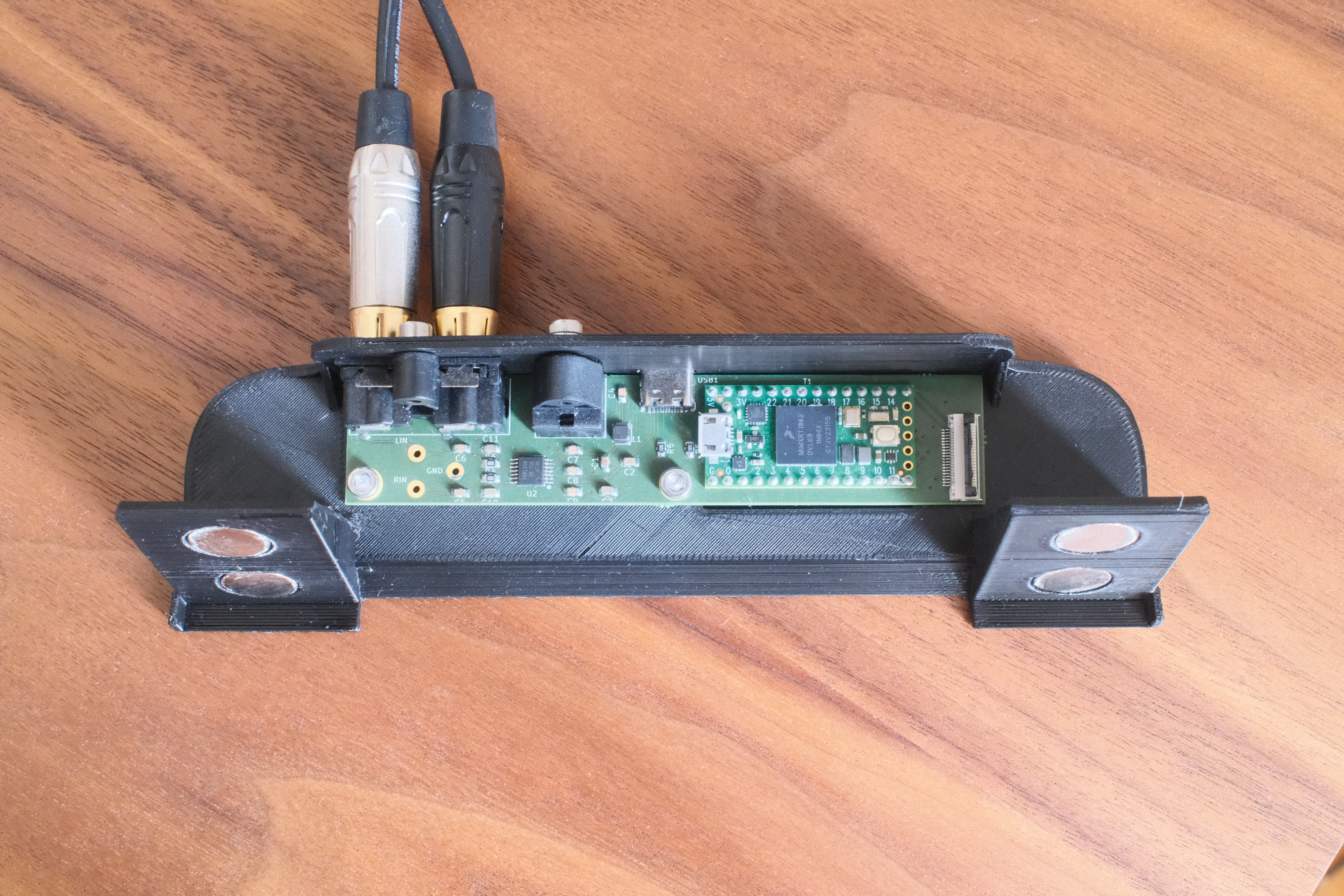
The final product